
Triggering Devices with an Arduino
Oscilloscopes, function generators, etc., usually come with a TTL-compatible trigger input. Most of the time, this input takes 5V signals, sometimes 3.3V signals. Typically, the input impedance is not specified. My Agilent arbitrary waveform generator uses 10kOhm input impedance.
TTL-compatible means that the inputs have a high impedance and that, by design, a single microcontroller output should be able to drive several inputs simultaneously (fan out).
How does a typical microcontroller perform as a trigger generator? I am using an Arduino Uno, which can drive 40mA per pin, with a slightly modifight blink example:
void setup() {
  pinMode(12, OUTPUT);
}

void loop() {
  digitalWrite(12, HIGH);   // Pin 13 has internal LED -> Use Pin 12
  delay(1);                 // 2x 1 ms -> 500Hz
  digitalWrite(12, LOW);
  delay(1);
}
I used clips and 1.5m of 50Ohm BNC cable to connect this to my oscilloscope (which has standard high-impedance inputs). For my measurements I did not connect this signal anywhere else: There was no trigger input listening. But routing this signal further to the TRIG-IN of a function generator did not change its properties too much - most of it was additional ringing caused by the extra cable. The following description applies to both cases.
The rising edge of my ~500Hz signal looks surprisingly clean, considering that the 50Ohm cable is not matched to the output and input impedances of the signal. The slew-rate is between 0.5V/ns and 1.0V/ns, the rise-time 10ns. You see some slight ringing of the cable in the first 100ns.
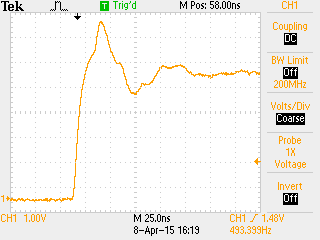
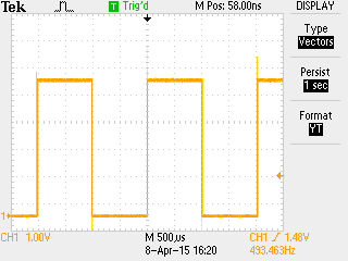
I did not try to measure the exact frequency. My scope gave me a value of 490Hz-495Hz, which I attribute to measurement error of the scope itself.
Looking at the edge of the next period, 2ms later, reveals a surprising amount of jitter. My el-cheapo oscilloscope does not have jitter-analysis software, but my impression was that most jitter is within ±150ns, with occasional spikes up to ±10µs, sometimes even more.
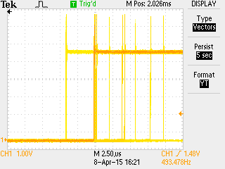
After 10 periods, the jitter got worse by a factor 2 or so.
Overall, using Arduino as a trigger generator seems to work for experiments where several 10µs jitter is OK. In my case, up to 1ms is acceptable, so I went with it.
For demanding applications, it's better to use a proper trigger generator that is designed to drive 50Ohm loads, so that the trigger inputs can be terminated properly. This reduces reflections (ringing). (If you use a 50Ohm driver, you should terminate the signal, otherwise you get twice the voltage!).
In practice, trigger inputs are rarely driven by 50Ohm or terminated properly, because the effects of reflections are very repeatable, which means that they don't matter a lot for the timing.